Extracting Non‐Planar Views from Spheres and Cylinders
Two non-planar views — Sinusoidal and Equirectangular — are available for projecting the surface of a sphere to a flat image (see Spherical Projections), while cylindrical projections represent meridians as straight, evenly-spaced vertical lines and circles of latitude (parallels) as straight horizontal lines (see Cylindrical Projections).
-
Add a Sphere or Cylinder shape to the workspace (see Adding and Editing Shapes).
Note In most cases, it is best to work in a workspace that includes both 2D reformatted views and a 3D view.
- Adjust the shape with the anchors so that the shape follows the surface that you want to inspect.
- Select a view in the workspace.
-
With the shape selected in Data Properties and Settings panel, choose Non‐planar 2D view in the View mode drop-down menu in the Scene’s Views Properties panel, as shown below.
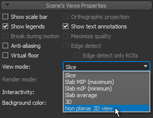
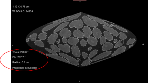
The non-planar view extracted from the surface of the sphere or cylinder appears.
-
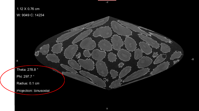
Examine the non-planar view. You should note that additional interactive text annotations, circled below, are available for manipulating non-planar views extracted from spheres and cylinders.
Theta… Lets you rotate the view around Theta (North Pole position).
Phi*… Lets you rotate the view around Phi (Equator position).
Radius… Lets you adjust the radius of the sphere or cylinder.
Projection*… Lets you toggle the view from Equirectangular to Sinusoidal and vice versa.* For Spherical projections only.
- Extract a projection of the non-planar view, if required (see Extracting Projections from Non‐Planar Views)